20+ block diagram ic 555
The NE555 contains 24 bipolar transistors two diodes and 15 resistors that form six functional blocks. From the above figure three 5k internal resistors act as voltage divider providing bias voltage of 23 Vcc to the upper comparator 13 Vcc to the lower.

How To Build A Mobile Jammer Circuit Without Ic S Quora
The 555 Timer IC.

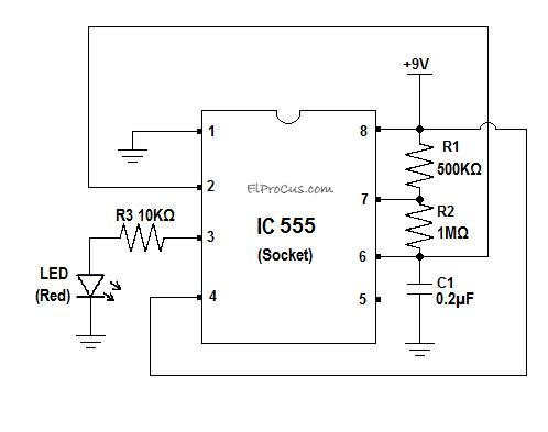
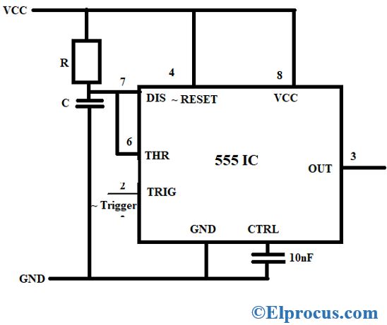
. This circuit is simplest one of all 3 modes of operationIn this circit R2 is connected between pin 8 and pin 2 and push button 1 is connected. The Upper comparator-UC is a Non-Inverting comparator compares the input signal with 23Vcc and Lower comparator-LC is an. Between the supply voltage VCC and the ground.
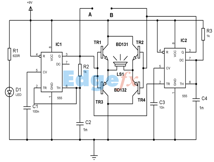
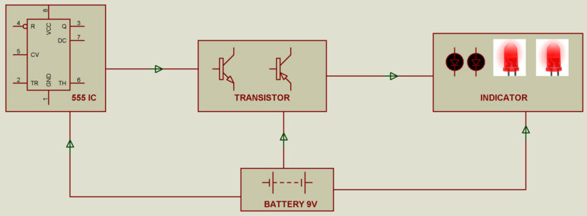
As shown in figure IC555 includes two comparators one RS flip-flop and other few discrete components like transistors. The output of 555 is used to drive load controlling devices such as transistors and relays. The thermistor is a variable resistor its resistance change according to the changing of.
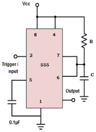
There are two ways of connecting load to output terminal. The timer basically operates in one of two modes. Bistable Mode of operation of 555 timer.
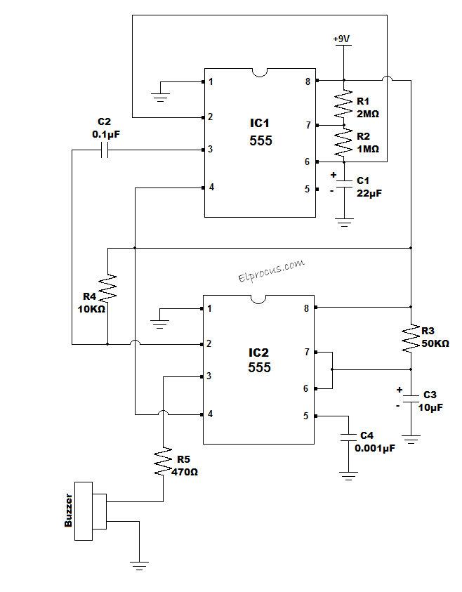
The 555 Timer IC is an 8 pin mini Dual-Inline Package DIP. The key component of the circuit is Thermistor transistor 555 Timer IC and Buzzer. As shown in the block diagram the phase locked feedback loop is not internally connected.
The 555 is a monolithic timing circuit that can produce accurate highly stable time delays or oscillation. Internal Block diagram of 555-Timer. The 555 Timer IC is an 8 pin mini Dual-Inline Package DIP.
The significance of each pin is self-explanatory from the. The pin diagram of a 555 Timer IC is shown in the following figure. The following figure shows the functional diagram of timer IC 555.
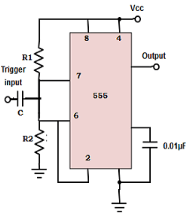
Either between output terminal pin 3 and. Block Diagram of 555 Timer IC.

Logic Circuit For Door Operation Using 555 Timer Download Scientific Diagram

Scheme Of 555 Timer Based Oscillator Used To Measure The Resistance Of Download Scientific Diagram
Ic 555 Timer Pin Daigram With Configuration And It S Applications
Ic 555 Timer Pin Daigram With Configuration And It S Applications
What Is Ic555 Quora
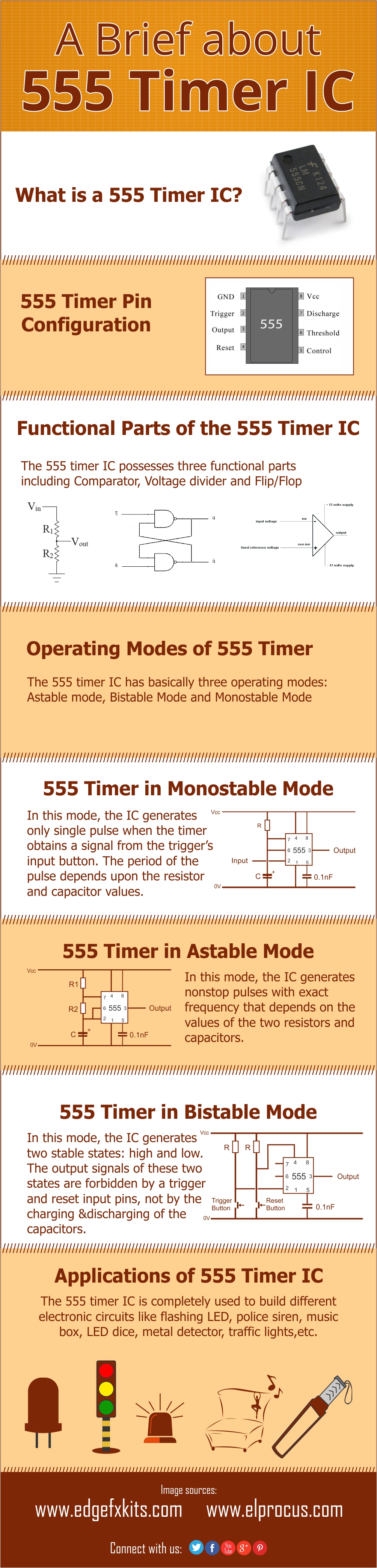
An Introduction About Ic 555 Timer Its Features And Appliations
Ic 555 Timer Pin Daigram With Configuration And It S Applications
Clap Switch Circuit Diagram Working And Its Applications
555 Timer As A Monostable Multivibrator Questions And Answers Sanfoundry

Pin On Electronics Knowledge

The 555 Timer Based Alarm Circuit With Automatic Reset And Multiple Download Scientific Diagram
Breadboard Projects For Beginners And Engineering Students

The General 555 Timer Circuit Schematic At The Heart Of The Circuit Is Download Scientific Diagram
Automatic Led Emergency Light Circuit Diagram Using Ldr In 2022 Led Emergency Lights Emergency Lighting Electronic Circuit Projects
555 Timer As A Monostable Multivibrator Questions And Answers Sanfoundry

The General 555 Timer Circuit Schematic At The Heart Of The Circuit Is Download Scientific Diagram

Types Of Relays And Relay Driver Circuit Buchholz Relay Relay Electronics Projects Electronic Parts